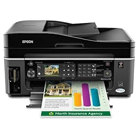
Epson WorkForce 610 Color Inkjet All-In-One Printer

This remarkable product manages to print documents up to two-times faster than leading color inkjet alternatives from competitive companies...

Activate Account Administrator di Windows 7 dan Vista : > "Run as administrator"...

HOW TO COPE VIRUS SHORTCUT 1234 RUNMIT

The characteristics of affected Virus 1234 Shortcut: 1. Shortcut Virus 1234 Runmit WATERMARK.EXE this will make the existing file in two places, namely:...

HOW TO SOLVE ERROR C000 ON CANON PIXMA MX870

How to solve error C000 on Canon Pixma MX870 Solution 1: Switch off the printer Disconnect the power cable Open door: ....

SPESIFIKASI TOSHIBA SATELLITE L645-1147XB

Spesifikasi Laptop Toshiba Satellite L645-1147XB O/S: Microsoft Windows 7 Home Premium Processor: Intel® Core™ i5-480M Processor (2.67 GHz, Cache 3 MB). Chipset: Intel HM55. Memory: 2 GB DDR3 SODIMM PC-8500, Max. Memory 8 GB (2 DIMMs) Graphics Engine: ATI Mobility Radeon HD 5470 512 MB...

Tuesday, April 12, 2011

Resetter All Epson

Resetter All Epson

SSC Service Utility  versi 4.30. Click here  download.


SSC SERVICE UTILITY SUPPORT FOR :

Monday, April 11, 2011

Epson WorkForce 610 Color Inkjet All-In-One Printer


This remarkable product manages to print documents up to two-times faster than leading color inkjet alternatives from competitive companies


Whether you are currently in the market for an exceptionally productive color inkjet printer for your office or home, Epson’s WorkForce 610 Color Inkjet All-In-One Printer provides you incomparable performance at an affordable price. You have the opportunity to capitalize on a limited time offer at Epson.com to purchase the Epson WorkForce 610 Inkjet All-In-One Printer for just $129.99 after sending in your $70.00 instant rebate.

Sunday, April 10, 2011

Is Your Printer Ready for Windows 7?

With Windows 7 officially available, complaints about lack of support for printers likely won't be far behind. But the good news is that you have a much better chance of moving your printer to Windows 7 without serious problems than you had going from XP to Vista. Granted, that's not a particularly high bar to clear, but after all the problems with printers and Vista, both Microsoft and most printer manufacturers have made an effort to make the move to Windows 7 easier. Judging by my tests, they seem to have succeeded. Unfortunately, that doesn't mean there isn't anything left to worry about.

Saturday, April 9, 2011

How to reset waste ink tank for a Canon Bubble jet I965

How to reset waste ink tank for a Canon Bubble jet I965

Solution:

Friday, April 8, 2011

Fixing Error Code 241 Paper Jam on Lexmark printers

Fixing Error Code 241 Paper Jam on Lexmark printers

Solution 1:

Wednesday, April 6, 2011

Fixing error code 0xb9000009165, 0xb9000009 on HP printers


Message looks like:

Error 0xb9000009 165hw interrupt hwv2.c is
Problem with the HP printer


Solution 1:


- Uninstall all the HP drives and software

- Unplugg the USB cable from the printer

- Unplugged power supply from the outlet and printer

- Plugg the USB back in to printer

- Unplugg the power supply from the power module.

- Plugg the power supply cord to module

- Plugg the power supply in to outlet

- Plug the power module connector to printer.


Solution 2:

- Unplugg the power and usb cable from the printer

- Download and install the lastest drivers and software for the printer


- Plugg the power and then the USB.


How to solve error C000 on Canon Pixma MX870


How to solve error C000 on Canon Pixma MX870

Solution 1:


  1. Switch off the printer


  2. Disconnect the power cable


  3. Open door:


  4. Remove the orange protective tape (A) and remove the white polystyrene (protective equipment) (B).


  5. Verify in the printer there is no protective equipment:


  6. Close the door.


  7. Connect the cable and switch on.


Solution 2 :

- Check for any foreign body in the printer: piece of paper, paper clip...

- Check for any paper jams.


Solution 3:

- This error code C000 could be made by an empty cartridge: check for this.


Monday, April 4, 2011

Hi-Speed 7 Port USB 2.0 Hub +Power AC Adapter for PC

Product Description


This 7 port USB hub should be the easiest and fastest way to connect all your USB devices to PC, laptops. 7 high-speed ports can connect to an almost limitless number of USB devices including modems, scanners, printers, PC cameras, digital cameras, keyboards.Specially designed for space-saving function and multi-connection convenience. Each port handles up to 480Mbps; these devices are fully hot-swappable and daisy-chainable up to 127 devices. The LEDs help color-code your USB devices and ports. Plug this hub into just one of your computers USB ports and you'll add 7 extra USB ports to your computer. This USB 2.0 7-port hub gives you more flexibility of connections. It comes with an AC power adapter so you can run devices like external drives, printers.


Product Details


* Brand: HDE


Features


* USB 2.0 and USB 1.1 compliant and USB-IF certified. Supported data speed: 1.5/12/480 Mbps. One upstr

* 8 luminescent LED lights. USB Powered. Over-current detection and protection for each downstream por

* Hot-swappable plug & play connection. Daisy-chain connection of up to 127 devices. Dimensions: 100 x

* Work with Windows 98/NT/2000/ME/XP. Package content: 1 x hi-speed 7-port hub with led lights, 1 x US


Tuesday, March 29, 2011

Minolta 1080 error code list


Minolta 1080 error code list


C000 Main drive problem
C001 Main drive speed. Too fast or too slow
C004C Fan motor problem
C004E Power supply fan problem
C0070 Toner motor drive problem
C0071 Toner motor speed. Too fast or too slow
C010 Drum motor drive problem
C011 Drum motor speed. Too fast or too slow
C0400 Exposure lamp does not turn on or AE sensor problem
C0500 Low fuser temperature during warm-up
C0510 Low fuser temperature after warm-up
C0520 High fuser temperature
C0600 Scan motor drive problem
C0610 Lens motor drive problem
C0620 Mirror motor drive problem
C0990, C0991 Main tray up problem
C0992, C0993 Main tray down problem
C0994 Elevator motor problem
C0996 Main tray shift problem
C0998 Tray shift problem
C0999 Tray shift return problem
C099A, C099b Shift home problem
C099c Shift drive motor
C0b10 Auto exposure sensor problem
C0b11 Paper clamp motor
C0b30 Paper aligning motor
C0b31 Paper aligning motor
C0b50 Stapler motor
C0b51 Stapler problem
C0b52 Stapler sensor
C0b60 Sorter bin motor
C0b61-C0b64 Sorter bin movement
C0d00 Duplex rail sensor sensor problems
C0d20 Duplex home sensor
C0d50 Duplex drive motor problem
C0d51 Duplex drive motor speed
C0F10 Auto exposure sensor problem
C0F30 Paper aligning motor
C4100 Exposure lamp stays on
C0F79 Paper empty sensor problem


Thursday, March 24, 2011

How to replace the belt on HP Designjet 5000 series


Remove the left hand cover:


Switch off the Printer and remove the power cable.

1. Remove ALL the Ink Cartridges from the Printer.

2. Open the Top Cover.

3. Open the door at the back of the Left Hand Cover.

4. Disconnect the Electrical Cable from the rear of the Ink Cartridge Tube Connector.


5. Disconnect the Air Tube.


6. Twist the 3 latches at the rear of the Ink Cartridge Tube Connector and release the complete Assembly.


7. Remove the Ink Cartridge Tube Connector and place safely on the window.


8. Remove 1 T-15 screw (Type F) from the Left Hand Cover (rear).


9. Close the Left Back door and remove 1 T- 25 screw (Type U) from bottom side (rear) of Left Hand Cover.


10. Remove 3 T-15 screws (Type F) from the Left Hand Cover (front).


11. Remove the Left Hand Cover from the Printer. When handling the Tubes make sure you do not damage them by twisting.


Remove the right rear cover:


1. Remove one T-15 screw (Type B) from the Right Rear Cover.


2. Remove the Right Rear Cover.


Remove the right hand cover:


To remove the Right Hand Cover you must open the Right Cover

door and push in the Printhead Cleaner Carriage.

1. Remove the Right Rear Cover

2. Remove the Ferrite and disconnect the Front Panel cable from the Main PCA from the left side of the Electronics Module.

3. On the Main PCA, disconnect the Aerosol Fan cable from position P30 and the service station door from

position P29. Take care not to drop the Cover when removing the screws. Support the Cover throughout the next step.


4. Remove 1 T-15 screw (Type F) and 1 T-25 screw (Type U) (bottom) from the rear of the Right Hand Cover.


5. Open the Top Cover.

6. Raise the Media Lever.


7. Remove 3 T-15 (Type F) screws from the front of the Right Hand Cover.


8. To release the cables, pull out the Right Hand Cover until the cables can be accessed.


9. Remove the Right Hand Cover.


Remove the tensioner assembly:


1. Remove the Left Hand Cover

2. Remove the Right Hand Cover

3. Remove the 5.5 mm nut from the left hand side of the Printer that attaches the Encoder Strip to the Spring Clip. TIP The next step is performed by putting pressure on the Spring Clip as shown.


4. Release the Encoder Strip from the retaining pin on the Spring Clip.


5. Using a screwdriver, fully tighten the Spring Release Screw to release the tension on the Belt.


6. From the right-hand side, lift the Tensioner Belt off the Scan-Axis Motor.


7. Remove 1 T-15 screw (Type L) from the Tensioner Assembly.


8. Remove the Belt Wheel on the left side.


9. Remove the Tensioner Assembly from the left-hand side.


Removing carriage assembly and belt:


1. Remove the Left Hand Cover

2. Remove the Right Rear Cover

3. Remove the Right Hand Cover

4. Remove the Tensioner Assembly

5. Pull out Printhead Cleaner Carriage.


6. Slide Carriage Assembly to position shown.


7. Lift up the Carriage Cover and remove ALL the Printheads and close the Carriage Cover.


8. Slide the Carriage along the Printer to the position shown.


9. Push in the 2 retaining clips either side of the Printhead Tube Connector.


10. Pull the Printhead Tube Connector towards you.


11. Push the button to release the Printhead Tubes in the Carriage.


12. Release the retaining clip by pulling it away from the holding brackets.


13. Pull the Printhead Tube Connector up between the two Tube Guides.


14. Slide the Carriage to the left side of the Printer.


15. Unclip and remove the Carriage Cover to access the Trailing Cable in the Carriage.


16. Carefully disconnect the Trailing Cables (3) from the connectors in the Carriage PCA.

NOTE Remove Trailing Cable Ferrites if they fall into the Carriage


17. Remove the Trailing Cables from the Trailing Cable Holder. TIP Press the Trailing Cables

firmly in the center to release.


18. Slide the Trailing Cable Guide out of the Carriage.


19. Slide the Carriage (including the Belt) to the left and out of the Printer.


20. Remove the Belt from the Carriage by releasing it from the retaining clips underneath the Carriage.


Installation of Carriage and Belt:


Before installation, clean and oil the Slider Rods using the User’s Slider Rods Lubrification Kit. Make sure you install the Carriage Assembly and Belt as follows:

1. Insert belt as indicated on the underside of Carriage.An arrow on the bottom of the Carriage indicates position and direction.


2. Line up the Carriage Guide, on the underside of the carriage, with the Slider Rods on the Printer.


Before installing the Carriage Assembly, remove the EMC Covers and check if there are Locating Pins for the Encoder Strip present at the rear of the Printer.

a If there are Locating Pins present, then you must break the Encoder Guide at the rear of the Carriage Assembly and then go to step 4 to install the Carriage Assembly.


b If there are no Locating Pins present, then go to step 4 to install the Carriage Assembly.


3. If you install the Carriage Assembly with the Encoder Guide broken off, then install the Encoder Strip by

inserting it into the Encoder Sensor at the rear of the Carriage Assembly as shown in this figure.


4. If you install the Carriage Assembly with the Encoder Guide, then install the Encoder Strip by sliding it into the Encoder Sensor at the rear of the Carriage Assembly as shown in this figure.


Related Posts Plugin for WordPress, Blogger...