Remove the left hand cover:Switch off the Printer and remove the power cable.
1. Remove ALL the Ink Cartridges from the Printer.
2. Open the Top Cover.
3. Open the door at the back of the Left Hand Cover.
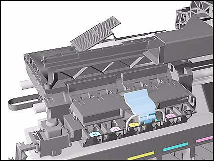
4. Disconnect the Electrical Cable from the rear of the Ink Cartridge Tube Connector.
5. Disconnect the Air Tube.
6. Twist the 3 latches at the rear of the Ink Cartridge Tube Connector and release the complete Assembly.
7. Remove the Ink Cartridge Tube Connector and place safely on the window.
8. Remove 1 T-15 screw (Type F) from the Left Hand Cover (rear).
9. Close the Left Back door and remove 1 T- 25 screw (Type U) from bottom side (rear) of Left Hand Cover.
10. Remove 3 T-15 screws (Type F) from the Left Hand Cover (front).
11. Remove the Left Hand Cover from the Printer. When handling the Tubes make sure you do not damage them by twisting.
Remove the right rear cover:
1. Remove one T-15 screw (Type B) from the Right Rear Cover.
2. Remove the Right Rear Cover.
Remove the right hand cover:
To remove the Right Hand Cover you must open the Right Cover
door and push in the Printhead Cleaner Carriage.
1. Remove the Right Rear Cover
2. Remove the Ferrite and disconnect the Front Panel cable from the Main PCA from the left side of the Electronics Module.
3. On the Main PCA, disconnect the Aerosol Fan cable from position P30 and the service station door from
position P29. Take care not to drop the Cover when removing the screws. Support the Cover throughout the next step.
4. Remove 1 T-15 screw (Type F) and 1 T-25 screw (Type U) (bottom) from the rear of the Right Hand Cover.
5. Open the Top Cover.
6. Raise the Media Lever.
7. Remove 3 T-15 (Type F) screws from the front of the Right Hand Cover.
8. To release the cables, pull out the Right Hand Cover until the cables can be accessed.
9. Remove the Right Hand Cover.
Remove the tensioner assembly:
1. Remove the Left Hand Cover
2. Remove the Right Hand Cover
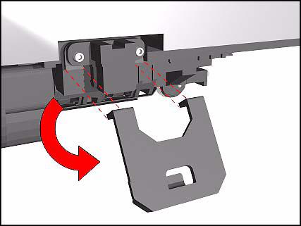
3. Remove the 5.5 mm nut from the left hand side of the Printer that attaches the Encoder Strip to the Spring Clip. TIP The next step is performed by putting pressure on the Spring Clip as shown.
4. Release the Encoder Strip from the retaining pin on the Spring Clip.
5. Using a screwdriver, fully tighten the Spring Release Screw to release the tension on the Belt.
6. From the right-hand side, lift the Tensioner Belt off the Scan-Axis Motor.
7. Remove 1 T-15 screw (Type L) from the Tensioner Assembly.
8. Remove the Belt Wheel on the left side.
9. Remove the Tensioner Assembly from the left-hand side.
Removing carriage assembly and belt:
1. Remove the Left Hand Cover
2. Remove the Right Rear Cover
3. Remove the Right Hand Cover
4. Remove the Tensioner Assembly
5. Pull out Printhead Cleaner Carriage.
6. Slide Carriage Assembly to position shown.
7. Lift up the Carriage Cover and remove ALL the Printheads and close the Carriage Cover.
8. Slide the Carriage along the Printer to the position shown.
9. Push in the 2 retaining clips either side of the Printhead Tube Connector.
10. Pull the Printhead Tube Connector towards you.
11. Push the button to release the Printhead Tubes in the Carriage.
12. Release the retaining clip by pulling it away from the holding brackets.
13. Pull the Printhead Tube Connector up between the two Tube Guides.
14. Slide the Carriage to the left side of the Printer.
15. Unclip and remove the Carriage Cover to access the Trailing Cable in the Carriage.
16. Carefully disconnect the Trailing Cables (3) from the connectors in the Carriage PCA.
NOTE Remove Trailing Cable Ferrites if they fall into the Carriage
17. Remove the Trailing Cables from the Trailing Cable Holder. TIP Press the Trailing Cables
firmly in the center to release.
18. Slide the Trailing Cable Guide out of the Carriage.
19. Slide the Carriage (including the Belt) to the left and out of the Printer.
20. Remove the Belt from the Carriage by releasing it from the retaining clips underneath the Carriage.
Installation of Carriage and Belt:Before installation, clean and oil the Slider Rods using the User’s Slider Rods Lubrification Kit. Make sure you install the Carriage Assembly and Belt as follows:
1. Insert belt as indicated on the underside of Carriage.An arrow on the bottom of the Carriage indicates position and direction.
2. Line up the Carriage Guide, on the underside of the carriage, with the Slider Rods on the Printer.
Before installing the Carriage Assembly, remove the EMC Covers and check if there are Locating Pins for the Encoder Strip present at the rear of the Printer.
a If there are Locating Pins present, then you must break the Encoder Guide at the rear of the Carriage Assembly and then go to step 4 to install the Carriage Assembly.
b If there are no Locating Pins present, then go to step 4 to install the Carriage Assembly.
3. If you install the Carriage Assembly with the Encoder Guide broken off, then install the Encoder Strip by
inserting it into the Encoder Sensor at the rear of the Carriage Assembly as shown in this figure.
4. If you install the Carriage Assembly with the Encoder Guide, then install the Encoder Strip by sliding it into the Encoder Sensor at the rear of the Carriage Assembly as shown in this figure.